Customise Consent Preferences

We use cookies to help you navigate efficiently and perform certain functions. You will find detailed information about all cookies under each consent category below.

The cookies that are categorised as "Necessary" are stored on your browser as they are essential for enabling the basic functionalities of the site. ... 

Always Active

Necessary cookies are required to enable the basic features of this site, such as providing secure log-in or adjusting your consent preferences. These cookies do not store any personally identifiable data.

No cookies to display.

Functional cookies help perform certain functionalities like sharing the content of the website on social media platforms, collecting feedback, and other third-party features.

No cookies to display.

Analytical cookies are used to understand how visitors interact with the website. These cookies help provide information on metrics such as the number of visitors, bounce rate, traffic source, etc.

No cookies to display.

Performance cookies are used to understand and analyse the key performance indexes of the website which helps in delivering a better user experience for the visitors.

No cookies to display.

Advertisement cookies are used to provide visitors with customised advertisements based on the pages you visited previously and to analyse the effectiveness of the ad campaigns.

No cookies to display.

Hangzhi Precision

How to Use Hangzhi Fluxgate Current Transducers

1. How to use AIT high precision fluxgate current transducers

Hangzhi high precision current transducer / sensor products were developed on the basis of Multi-Point Zero Flux Gate technology, which can be applied for both AC and DC current measurement application, with analogical current, digital signal via RS232/485 & 0-10V voltage output options available. All Hangzhi high precision current transducer / sensor products are CE EMC & RoHS compliant.

how to use AIT high precision fluxgate current transducer

Important Note:

The resistance connected to the output terminal of the sensor should be within the range specified in the datasheet.

(a) When the sensor does not pass current, the voltage on the resistor R is about 0V
(b) When the device is working normally after power on, the green indicator light is always on
(c) When the sensor passes a DC current, the voltage on the resistor R is:
U = Measured Current / Sensor Turns Ratio * Resistance R

If the output voltage is abnormal:

(a) First use a multimeter to measure the power supply of the sensor and check whether the power supply is wired correctly;

(b) Check whether the running indicator and the power supply indicator are displayed normally.

2. How to use HIT hall-effect replacement and IIT industrial fluxgate current transducers

2.1 How to wire HIT & IIT current transducer

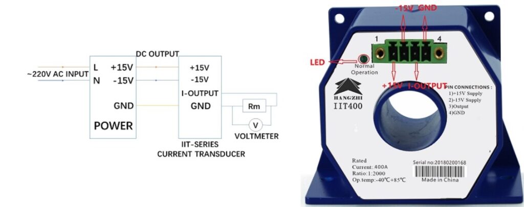
The wiring method of the HIT and IIT current transducer is almost the same, please find the details below:

However, there is no operation indicate LED on HIT current transducers.
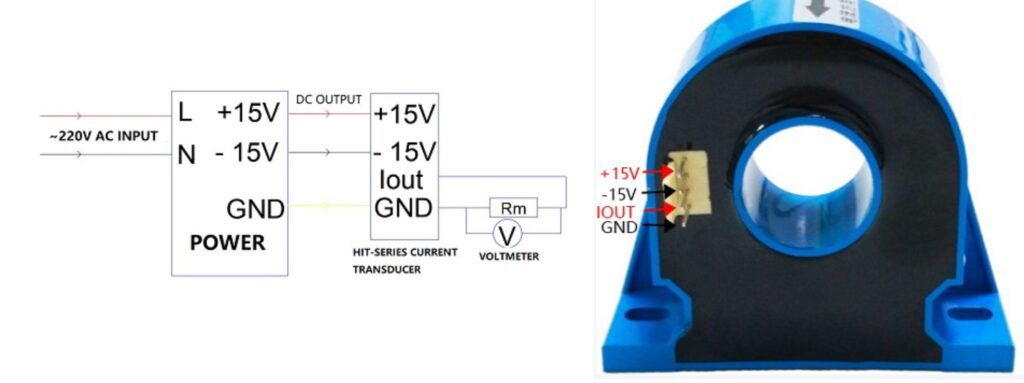
how to wire hit fluxgate current transducers
how to wire iit fluxgate current transducers

(2) Test method: 
The resistance connected to the output terminal of the sensor should be within the range specified in the datasheet. 

When the wiring is correct and working normally:
(a) When the sensor does not pass current, the voltage on the resistor Rm is about 0V;
(b) When the sensor passes a DC current, the voltage on the resistor Rm is:
U = Measured Current / Sensor Turns Ratio * Resistance Rm

3. How to use RIT leakage current transducers
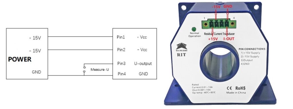
how to wire rit leakage current transcuders

3.2 How to measure with RIT leakage current transducer

(2) Test method: 
The output terminal of the sensor is connected to the voltage meter or analogical input module

When the wiring is correct and working normally:
(a) When the primary current is 0A, the output voltage of the sensor is about 0V;
(b) After the device is powered on, when the device is working normally, the green indicator light is always on;
(c) When the sensor passes DC current, the primary current Ip is:
Ip=Kn*Uoutput

If the current is abnormal or the power supply is abnormal:
(a) First use a multimeter to measure the power supply of the sensor and check whether the power supply is wired correctly;

Get in touch with our experts

Contact us directly via email info@hangzhiprecision.com or fill out the form below. We will respond as soon as possible.
en_CAEnglish (Canada)
We've detected you might be speaking a different language. Do you want to change to:
en_US English
en_US English
es_ES Español
pt_PT Português
fr_FR Français
de_DE Deutsch
ru_RU Русский
ar العربية
nl_NL Nederlands
tr_TR Türkçe
pt_BR Português do Brasil
en_CA English (Canada)
en_GB English (UK)
ko_KR 한국어
ja 日本語
en_AU English (Australia)
de_AT Deutsch (Österreich)
pl_PL Polski
nl_BE Nederlands (België)
fr_BE Français de Belgique
da_DK Dansk
sv_SE Svenska
de_CH Deutsch (Schweiz)
it_IT Italiano
en_ZA English (South Africa)
ro_RO Română
hu_HU Magyar
cs_CZ Čeština
fi Suomi
id_ID Bahasa Indonesia
es_AR Español de Argentina
es_CL Español de Chile
es_PE Español de Perú
es_MX Español de México
el Ελληνικά
Close and do not switch language
Let's chat on WhatsApp

How can I help you? :)

09:16